

A track-shoe connection can remain visually tight while repeated interface slip bends its bolts and starts cracks at the first loaded thread. I examine impact-loaded connections by asking where each service force travels, when contact pressure disappears, and how cyclic bolt stress changes. This article develops a verification approach for track, cutting-edge, crusher, and industrial-machine joints without confusing fastener strength designation with demonstrated fatigue performance.
A bolted connection can transfer external load through friction between clamped members, bearing between a shank and a hole, direct bolt tension, or a combination of these mechanisms. The intended mechanism must be explicit. A friction-dependent connection needs sufficient retained contact pressure to prevent unacceptable motion. A bearing connection needs verified hole geometry, local material resistance, and bolt capacity after contact develops. Unplanned transition between the mechanisms can accelerate damage.
Tightening stretches the bolt and compresses the joint. Under external separating force, bolt tension increases while member compression decreases. In a simplified elastic model before separation, bolt stiffness relative to member stiffness determines the incremental bolt load. This model needs qualification when the connection includes soft coatings, thin plates, eccentric forces, or nonuniform contact. Local opening may begin before the full interface loses contact.
Impact adds a time-dependent load path. The force experienced by a track joint depends on machine motion, contact geometry, support compliance, and load rise time. A peak measured elsewhere on the machine cannot automatically be assigned to every bolt. Conversely, a smooth nominal operating load may conceal local impacts when a loose interface strikes a clearance-hole edge. The test boundary conditions must reproduce the relevant connection behavior.
Fatigue depends on cyclic stress at the likely crack origin, including the influence of mean stress, geometry, and material condition. Preload can reduce the tensile stress variation associated with external load while the members remain compressed, but it also contributes to mean tensile stress. Raising preload indefinitely is therefore not an acceptable fatigue strategy. Thread capacity, combined tightening stress, seat resistance, and material susceptibility impose upper limits.
No technical standards were supplied, so no standard identifier, clause, certificate, or issuing body is introduced here. Verify the applicable fatigue qualification method, loading spectrum, and acceptance rules against current approved engineering and manufacturer test reports before specification. The mechanical relationships discussed are explanatory models rather than verified ratings for a particular product.
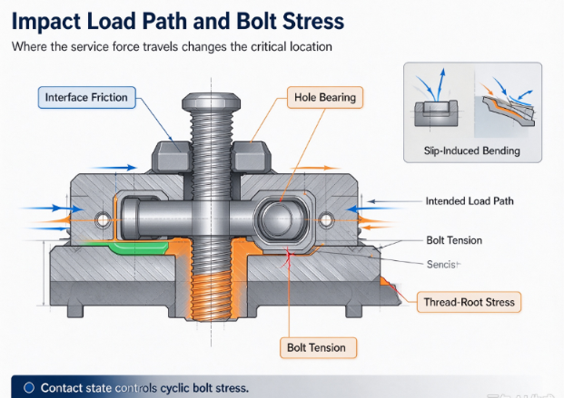
I select the inspection points from the load path. Track assemblies often emphasize contact retention and hole bearing; cutting-edge joints add abrasive contamination and uneven seats; crusher attachments can combine impact, bending, and inaccessible internal threads. The component descriptions below identify evidence to verify, rather than assume that one fastener configuration fits all three applications.
| Component | MaterialSpec | Function | Failure Risk if Compromised |
|---|---|---|---|
| Bolt grip and shank | Verify material, heat treatment, dimensions, and mechanical properties against the current lot report. | Carries tension and any designed shear or bending; establishes bolt stiffness. | Excessive cyclic stress, yielding, or fracture at a geometric transition. |
| Thread root and runout | Verify root geometry, manufacturing route, surface condition, and location relative to load planes. | Transfers force into the mating thread while maintaining the specified transition geometry. | Fatigue initiation under combined axial and bending stress. |
| Clamped contact faces | Verify member material, flatness, roughness, coating condition, and contamination limits. | Maintains compression and transfers the intended interface forces. | Slip, fretting, local separation, or rapid settlement. |
| Head and bearing support | Verify seating geometry, supporting hardness, washer condition, and contact area. | Introduces clamping force without unacceptable indentation or eccentricity. | Preload loss, head bending, or local member damage. |
| Mating thread system | Verify Nut compatibility or tapped-material strength and effective engagement. | Reacts bolt tension and preserves the axial load path. | Thread stripping or pullout during tightening or impact. |
| Locking and surface-treatment system | Verify approved locking mechanism, coating process, friction condition, and hydrogen-risk controls. | Limits specified rotation and protects surfaces within a qualified assembly condition. | False assurance of clamp retention, altered preload, or delayed fracture. |
Verify all parameters against current test reports and applicable standards before use in specifications.
A locking feature does not replace contact-pressure verification. It may restrain rotation while the compressed stack settles. Likewise, a plain shank positioned through a shear plane may improve a particular bearing load path, but it does not prove that the complete joint survives the service spectrum. Geometry, contact conditions, and material response must be evaluated together.
The test plan should distinguish installation qualification, joint response, and accumulated damage. I would establish the actual retained-preload condition before applying cyclic loads, then monitor displacement and force where the relevant mechanisms occur. A test that begins with unrepresentatively high preload can hide the slip mechanism that develops after service settlement.
| Parameter | Standard | Test Method | Acceptable Range | Implication if Out of Range |
|---|---|---|---|---|
| Service load spectrum | Not supplied; spectrum derivation requires approval. | Measure representative force histories and validate the joint-level load mapping. | Approved directions, amplitudes, sequence, and severity; verify numerical values. | An unrepresentative test may miss the dominant damage mechanism. |
| Retained clamp force | Not supplied; measurement procedure requires verification. | Measure before loading, during defined checkpoints, and after testing. | Above the joint-derived minimum and below component limits. | Opening or slip can increase cyclic bolt stress. |
| Interface slip | Not supplied; displacement criteria require verification. | Monitor relative displacement at relevant contact locations. | Within the approved functional and fatigue-related limit. | Fretting and repeated hole-edge impact alter the intended load path. |
| Local separation | Not supplied; opening criteria require verification. | Use qualified gap, displacement, or contact-response measurements under eccentric loading. | Within project-approved opening limits for each load case. | Bolt force and bending may rise beyond the assumed model. |
| Crack development | Not supplied; inspection method and resolution require verification. | Inspect expected origins during and after the approved cyclic sequence. | Meets the approved crack acceptance and detection requirements. | Progressive fracture can redistribute load across the bolt group. |
| Thread and bearing damage | Not supplied; dimensional criteria require verification. | Inspect internal threads, holes, seats, and residual deformation after loading. | Within approved geometry and residual-strength limits. | Apparent survival may conceal damage that prevents continued use. |
Verify all parameters against current test reports and applicable standards before use in specifications.
Define inspection sensitivity before testing. A statement that no cracks were observed is incomplete without the method, accessible surfaces, detection capability, and component condition. Preserve crack location relative to threads, runout, head fillet, and shear planes. If destructive examination is needed, identify which specimens represent the tested process and avoid treating a conveniently accessible surface as the only possible origin.
A passing test supports the configuration and conditions actually evaluated. Changes in grip, member thickness, surface treatment, mating material, or load direction may invalidate transfer to another machine. Record the approved configuration and explicitly assess whether each change preserves the stress distribution, retained contact, and failure mechanism. Do not extrapolate service life from a shortened test without a validated relationship.
The first protection mechanism is retention of the intended load path. For a joint designed to transfer shear through interface friction, available resistance depends on contact pressure, interface friction, and the geometry of loaded surfaces. Oil, worn paint, oxide debris, or polished contact regions can change that response. Bolt Preload cannot be considered independently of the surface condition through which the external force is transferred.
Tightening torque determines this initial state only through a qualified friction relationship. Dry threads, deliberate oiling, zinc coating, and repeated assembly can produce different clamp-force distributions at the same torque. I would measure torque and clamp force on representative assemblies and preserve the lot-specific results. An acceptance rule must address low-clamp outliers that permit slip and high-clamp outliers that overload threads or bearing surfaces.
Torque calibration and joint qualification answer different questions. Calibration addresses tool measurement or output accuracy under its defined conditions. Joint qualification addresses the force generated by that output in the actual connection. A highly repeatable tool can repeatedly create insufficient preload when friction is systematically high. Conversely, changing to a lubricated assembly can create excessive preload while every tightening record remains inside the previous torque window.
For track, cutting-edge, and crusher connections, impact-fatigue verification must include the actual force directions and moments. I examine whether the grip is short, whether the joint opens at one edge, and whether a shear plane crosses threads. Clearance after slip can introduce bending as the bolt contacts a hole edge. If the thread root lies in that region, its local stress can be much higher than an average shear calculation suggests.
A meaningful cyclic test reproduces the boundary stiffness and contact condition needed to activate the suspected mechanism. I would measure preload loss and interface motion during the sequence, then inspect likely crack origins. Strength designations alone cannot establish a fatigue margin because they do not define this connection's stress range, loading history, or contact behavior. A fracture near a loaded thread must be evaluated against the actual joint mechanics rather than attributed to vibration as an unexplained general cause.
Effective thread engagement must support both installation preload and subsequent dynamic demand. Exclude chamfers, incomplete threads, and damaged portions when establishing usable engagement. In a blind hole, verify that the bolt tip remains clear of the bottom and that the clamped stack can seat. False seating can leave the connection vulnerable to impact even though the assembly torque appears acceptable.
Compare internal-thread stripping, external-thread stripping, bolt tensile failure, and local member damage. Their relative capacities depend on mating material, thread geometry, and the actual load distribution. Longer engagement does not correct an incompatible or damaged thread automatically, and engaged turns do not carry identical loads. Destructive testing of representative mating components should document the failure location and support the proposed design margin.
Delayed fracture requires separate consideration when high-strength Steel Bolts receive processes that can introduce hydrogen. Material susceptibility, acid cleaning, electroplating, residual stress, and sustained assembly tension form part of the evaluation. Fatigue and hydrogen-related cracking can produce overlapping symptoms, and service history alone may not distinguish them. Fracture examination, hardness verification, and treatment records are needed before assigning a root cause.
Verify the hydrogen-relief procedure where applicable, including treatment timing, actual part-temperature evidence, duration, and traceability to the coating lot. Sustained-load testing must use an approved method with defined sampling and acceptance. Corrosion exposure assesses coating performance under its conditions; it cannot replace a delayed-fracture assessment. Reducing manufacturing hydrogen introduction also does not remove the need to evaluate hydrogen generated by relevant service corrosion conditions.
Protection therefore requires coordinated limits rather than a single instruction to tighten harder. An excessive assembly preload may suppress early slip but increase combined stress and delayed-fracture susceptibility. Insufficient preload may avoid immediate assembly damage while permitting damaging cyclic motion. The valid operating interval is the intersection of contact-retention requirements, component capacity, material condition, and verified installation scatter.
For a group of bolts, evaluate how local settlement or one damaged fastener changes the force distribution. A symmetric drawing does not guarantee equal load sharing when members bend or contact is uneven. The test should capture the critical position, including edge bolts exposed to prying. Acceptance must address the joint's continued function as well as the survival of isolated fasteners.
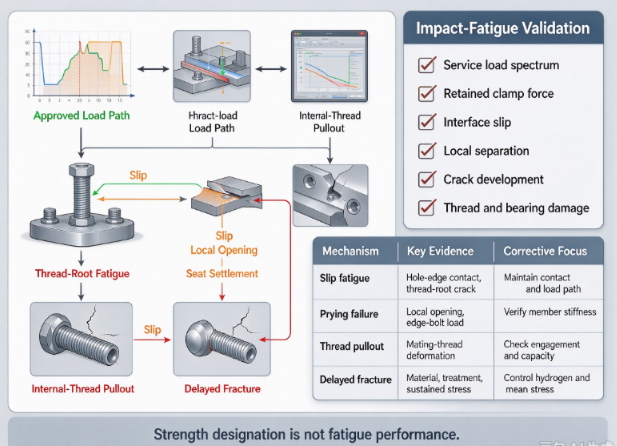
Failure: Cracks initiate near a thread located close to a shear plane. Root Cause: Lost contact pressure permits slip, and repeated hole-edge contact bends the threaded section. Engineering Consequence: Crack growth reduces the remaining section and can trigger sudden joint failure. Prevention: Verify retained preload, control the interface, and qualify the thread location within the actual load path.
Failure: An edge bolt fails while centrally located bolts remain intact. Root Cause: Eccentric loading bends the member and creates local opening, increasing force at the edge connection. Engineering Consequence: Load redistributes unevenly across the group. Prevention: Model member flexibility and confirm local separation and bolt-load distribution through representative testing.
Failure: Contact surfaces develop wear debris and polished motion bands. Root Cause: Oscillatory micro-motion occurs after preload loss or under an unqualified interface condition. Engineering Consequence: Wear changes surface geometry and can accelerate further clamp loss. Prevention: Define surface preparation, preload retention, and the permitted displacement response under cyclic loading.
Failure: A bolt remains largely intact while the housing thread tears out. Root Cause: Effective engagement and mating-material capacity are insufficient for the combined preloaded and dynamic load state. Engineering Consequence: The attachment loses restraint and damages the surrounding component. Prevention: Compare competing failure capacities and test the actual tapped material and geometry.
Failure: The joint loses contact pressure without obvious fastener rotation. Root Cause: Bearing indentation, compressed coating, or member settlement reduces the clamped stack thickness. Engineering Consequence: A rotation restraint masks the development of slip risk. Prevention: Measure force retention and qualify seat hardness, contact geometry, and coating behavior separately from rotation control.
Failure: A coated fastener fractures after assembly, sometimes before substantial operating exposure. Root Cause: Hydrogen-assisted cracking may develop under sustained tension in susceptible material. Engineering Consequence: Replacing only the broken component can leave the same batch-related mechanism unresolved. Prevention: Investigate treatment history and fracture evidence, then apply approved process and sustained-load controls.
Define force directions, impact events, moments, load combinations, and the intended service spectrum.
Identify whether shear transfers through friction, bearing, or a qualified combination.
Specify grip length, thread-runout location, shear planes, hole geometry, and member flexibility.
Verify retained preload, local opening, slip, bearing deformation, and fatigue acceptance limits.
Define the torque or alternative tightening method using current torque–clamp evidence.
Specify friction condition, lubricant application, rotating interface, and tightening sequence.
Separate new and reused assembly conditions unless qualification demonstrates equivalence.
Define seating verification and procedures for assemblies that show abnormal torque–angle behavior.
Identify abrasive contamination, water, corrosion media, and temperature changes.
Verify coating durability and its effects on friction, settlement, and hydrogen susceptibility.
Define inspection access and allowable degradation at seats, threads, and contact faces.
Confirm the applicable standards and editions before release; none were supplied for this article.
Require a traceable cyclic test configuration with approved spectrum, inspection method, and acceptance criteria.
Retain material, coating, heat-treatment, and sustained-load evidence for relevant lots.
Define change-control triggers for member geometry, friction condition, and mating material.
The supplied profile describes Ningbo yi teng construction machinery CO,LTD as a manufacturer established in 2005 with a focus on construction-machinery parts and fasteners, particularly Pins. It lists Track Bolts, cutting-edge bolts, Crusher Bolts, Nuts, Custom Fasteners, and hydraulic accessories, together with overseas market experience.
I evaluate any manufacturer by its ability to connect material and dimensional control to the intended dynamic connection. Relevant evidence includes thread-root inspection, heat-treatment consistency, torque–clamp characterization, mating-component tests, and traceability through surface treatment. Capability to examine fracture origins matters because repeating a tensile test on an unused bolt may not reproduce a joint-driven fatigue failure.
The technical-standards field does not establish a current certification. Verify any required certification for the correct holder, scope, and validity before specification. Engineering acceptance must remain tied to the tested configuration and failure mechanisms rather than a general quality statement.
The related product page should identify track, cutting-edge, and crusher bolt configurations together with the evidence required for impact-fatigue qualification.
A higher strength designation does not prove fatigue resistance in a particular joint. Fatigue depends on the local cyclic stress, mean stress, geometry, and contact state. Verify the actual connection under its approved load spectrum and retained-preload condition.
A locking device cannot prevent every vibration-related failure because rotation is only one route to connection degradation. Seat settlement and local opening can reduce effective restraint while the fastener remains rotationally secured. Verify both rotation control and retained contact pressure.
Locating threads outside a shear plane is insufficient without verifying the complete load path. The shank, hole, member, and bearing surfaces must still withstand the resulting forces. If slip or prying introduces bending elsewhere, the critical location may move rather than disappear.
A constant-amplitude test represents a variable service spectrum only when its equivalence has been justified. Sequence effects, overloads, and changing contact conditions can alter accumulated damage. Establish the approved relationship before using the result to support service-life claims.
A broken bolt should not be classified as fatigue from appearance alone. Preserve the fracture surfaces and relate microscopic evidence to load history, hardness, and treatment records. Hydrogen-assisted cracking, overload, and fatigue can require different corrective actions.
Share your project parameters for a technical review.
Contact person: Mr.Ren
Phone:0086-13958324455
Customer service: +86-0574 88065928
Email: Sales@zjbzj.com
Fax: +0086-0574 88065656

official website
Copyright @ Ningbo yi teng construction machinery CO,LTDmainly engaged in Blade Bolts Series, Hexagon bolt, and Bucket teeth. Welcome to inquire!
SitemapThis website uses cookies to ensure you get the best experience on our website.
 Español
 Portugues
 Pусский
 Français
 Deutsch
 日本語
 한국어
 العربية
 हिन्दी



 WhatsApp
 Phone
Comment
(0)